


A firefighting amphibian touches down on a lake at 65 knots, opens its scoop probes, and begins ingesting water at several hundred litres per second. For a large amphibian scooping twelve tonnes, the aircraft gains more than half its empty weight in under fifteen seconds while decelerating through the speed range where porpoising stability margins are thinnest. The centre of gravity shifts aft by as much as one metre, the equilibrium trim angle increases, and the hydrodynamic drag nearly doubles from scoop-capture forces alone.
The porpoising boundary is not a single curve but a family of curves parameterised by mass and CG position, and every second of the scooping run moves the aircraft from one member of that family to the next.
The same physics applies to any operation that changes mass or centre of gravity during water contact, whether that operation is a firefighting scoop, a fuel-burn-induced CG shift between outbound and return landing, or an asymmetric float loading on a twin-float seaplane. The scooping case simply compresses the problem into twelve seconds, which makes it both more tractable analytically and more demanding operationally.
The Porpoising Boundary in Calm Water
Porpoising is a coupled heave-pitch oscillation that arises from the phase lag between hydrodynamic forces and hull motion. A trim perturbation changes the wetted forebody length and thus the hydrodynamic lift, which induces a heave response, which in turn modifies the pitch through the cross-coupling terms in the equations of motion. When the energy fed into the oscillation by this coupling exceeds the hydrodynamic damping, the motion becomes self-sustaining. The oscillation frequency, which typically lies between 1 and 4 Hz for seaplane hulls, is set by the ratio of hydrodynamic stiffness to pitch inertia.
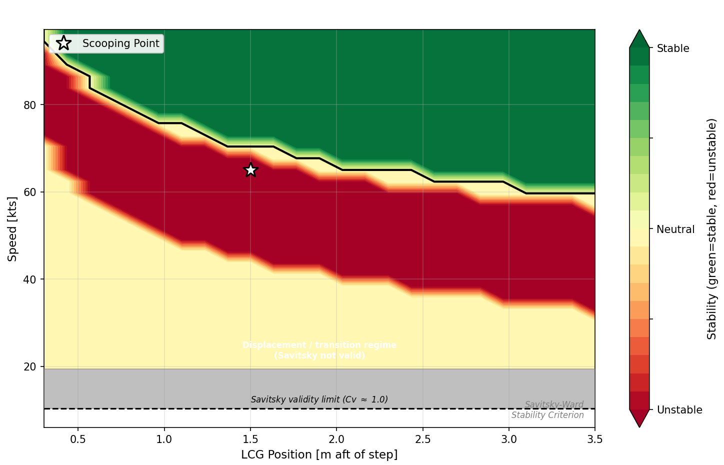
Smith and White [SW54] consolidated the experimental evidence from two decades of NACA and ARC tank testing into what remains the most comprehensive review of porpoising instability. Their stability diagrams plot trim angle against speed coefficient Cv = v/√(gb), where b is the hull beam. The stable operating region lies between an upper porpoising limit (above which the hull enters the nose-up instability cycle) and a lower limit (below which the hull digs into the bow). The width of this corridor depends on step loading CΔ = Δ/(ρgb³), afterbody keel angle, and afterbody length-to-beam ratio, and the boundary can be estimated analytically using the Savitsky-Ward stability criterion [Sav64].
The coupled heave-pitch equations in the linearised form used by Martin [Mar78], Sun and Faltinsen [SF11], and Ito et al. [Ito+16] read
The subscripts 3 and 5 denote heave and pitch. The Aᵢⱼ are added mass and added inertia terms, the Bᵢⱼ are hydrodynamic damping terms, and the Cᵢⱼ are restoring terms. Stability of the equilibrium requires all eigenvalues of this system to have negative real parts, which the Routh-Hurwitz criterion evaluates from the characteristic polynomial without requiring explicit eigenvalue computation.
For the present discussion, the important observation is where the centre of gravity enters these equations. It appears in three places, each with a different effect on the boundary.
Three Ways CG Moves the Boundary
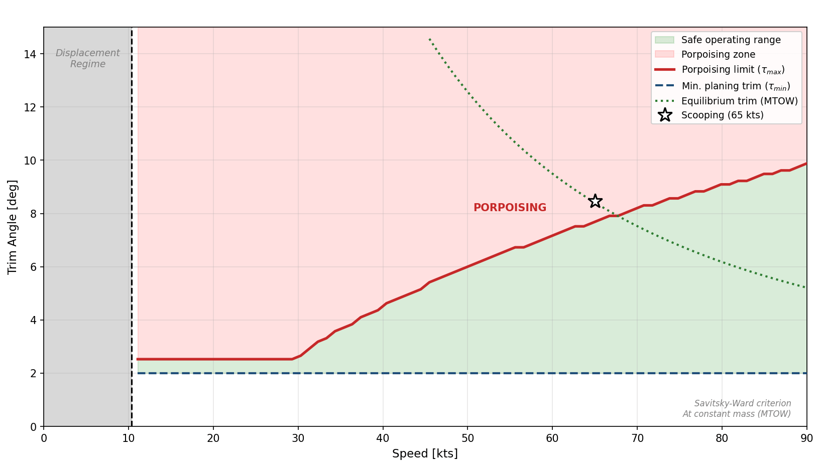
The first and most obvious effect is on equilibrium trim. At a given speed, a forward CG requires the hull to plane at a lower trim angle because the nose-down pitching moment from the CG offset must be balanced by hydrodynamic forces that increase with trim. Aft CG produces the opposite effect, increasing equilibrium trim. Since the porpoising boundary in the trim-speed diagram is a fixed curve for a given hull geometry and loading, changing the equilibrium trim moves the operating point relative to the boundary without moving the boundary itself.
Smith and White [SW54] quantified this effect from both model-scale and full-scale tests. On the Shetland flying boat hull, a forward CG shift raised the lower porpoising limit by approximately 3° at 50 knots while producing no measurable change above 70 knots. An aft CG shift narrowed the stable trim corridor to just 1.5° at 60 knots, which leaves almost no margin for pilot inputs or wave-induced perturbations. Their general conclusion was that forward and upward CG movement raises the lower limit but has little effect on the upper limit, while aft CG movement primarily narrows the overall stable range.
The second effect operates through step loading. When mass increases (as during scooping), CΔ increases proportionally because displacement Δ appears in the numerator. Higher CΔ generally shifts the porpoising boundary upward in the trim-speed diagram, which means the hull can tolerate higher trim angles before porpoising onset. This effect is stabilising in isolation, and it explains why heavily loaded hulls are sometimes more resistant to porpoising than lightly loaded ones, a result that surprises engineers accustomed to thinking of additional mass as universally detrimental.
The third effect is on pitch inertia. The pitch moment of inertia I₅₅ = mk²₅₅ changes both through the increased mass m and through the changed radius of gyration k₅₅ about the new CG. Water in tanks located away from the CG increases k₅₅ and thus increases I₅₅ more than proportionally to the mass increase. Higher pitch inertia reduces the natural frequency of the heave-pitch oscillation, which shifts the frequency at which resonant coupling occurs. Zan et al. [Zan+23] found in towing-tank tests on a planing trimaran that a 15% reduction in pitch inertia reduced porpoising oscillation amplitude by 60%, which demonstrates the sensitivity of this parameter.
These three effects do not act in the same direction. The CG shift toward the tanks (typically aft for firefighting amphibians) moves the operating point toward higher trim, which is usually destabilising by approaching the upper porpoising limit, though for a hull that operates near the lower limit at light load an aft CG shift can be stabilising by moving the operating point away from it. The mass increase raises CΔ, which is stabilising. The inertia change may go either way depending on tank geometry. The net effect depends on the specific hull design and tank arrangement, which is why a generic statement about whether scooping is stabilising or destabilising cannot be made without calculation.
What Happens During the Scoop Run
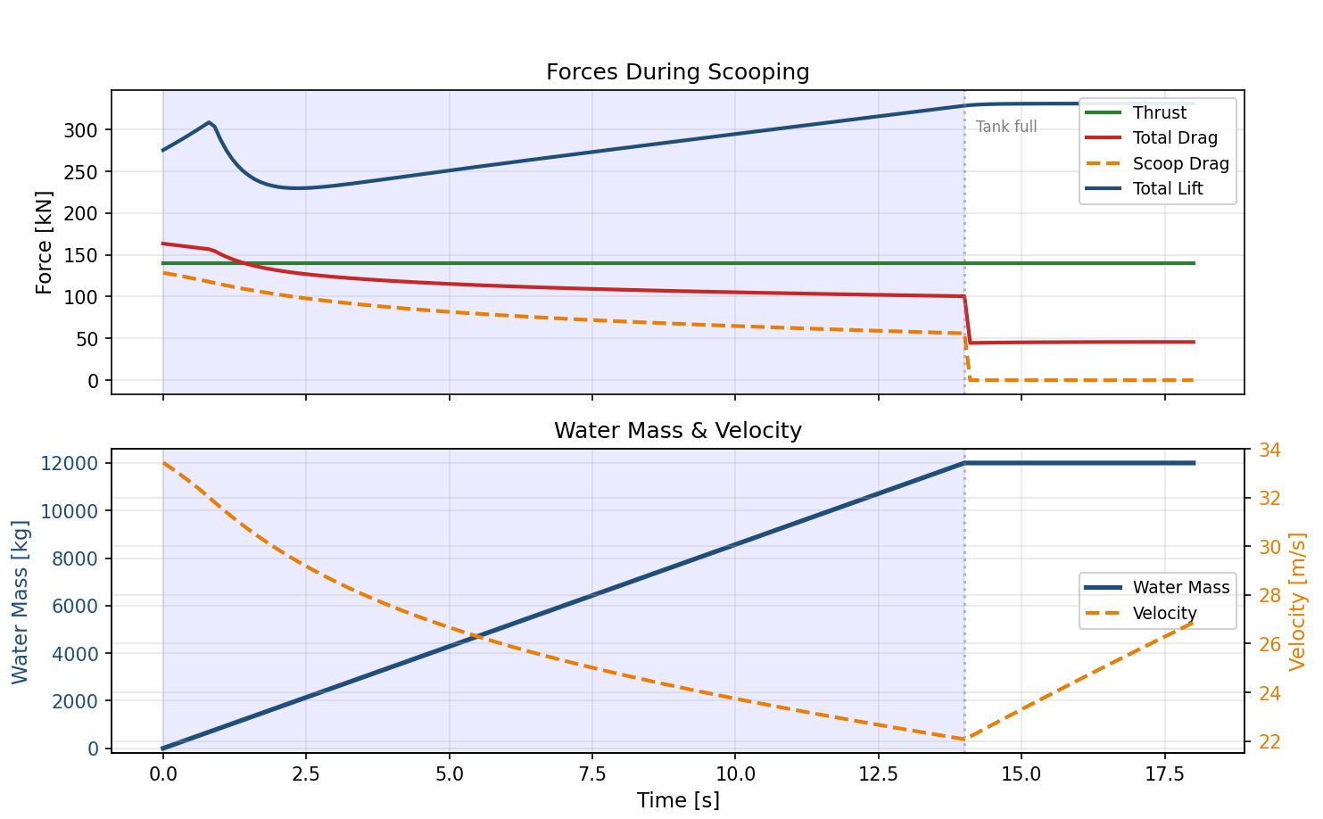
The scooping run is not a quasi-static process. Over approximately twelve to fourteen seconds, the aircraft traverses a path through the stability diagram that involves simultaneous changes in speed, mass, CG position, drag, and trim. Calculations using SILAS (Stability Investigation and Load Analysis for Seaplanes), a seaplane hydrodynamics framework developed by the author, for a representative heavy amphibian hull (twin ram-pressure probes, water capacity of the order of 12 tonnes) illustrate the force balance during a scooping run initiated at 65 knots.
At the start of the run, the scoop probes deploy and ram pressure drives water into the tanks. The scoop-capture drag at the initial speed is of the order of 100 kN, which is comparable to the hull hydrodynamic drag itself. For this calculation, thrust was assumed constant, which means the aircraft decelerates as drag increases. Over the twelve-second fill period, speed drops from roughly 33 m/s to approximately 22 m/s, while mass increases quasi-linearly from the operating empty weight to the loaded condition.
The deceleration changes the stability picture in a speed-dependent way. Above hump speed, the stable trim corridor generally widens as speed decreases, but near hump speed the corridor narrows to its minimum, which means that an aircraft decelerating through the hump during scooping passes through the region of least stability margin. The aircraft is simultaneously becoming heavier (higher CΔ, stabilising), slower (potentially stabilising or destabilising depending on speed regime), and more aft-CG (higher equilibrium trim). Whether the net trajectory moves toward or away from the boundary depends on the relative rates of these changes and on where in the speed range the scooping occurs, which requires evaluating the stability criterion across the full transient rather than at a single operating point.
The time-resolved scooping data that would allow external validation of such calculations are not publicly available. Calbrix et al. [Cal+23] noted explicitly that detailed flow rate measurements for the CL-415 remain confidential. Mean scooping rates can be estimated from published tank volumes and fill times (roughly 450 L/s for the CL-215, 500–560 L/s for the CL-415, 850 L/s for the Be-200, and over 1,000 L/s for the Martin Mars), but the instantaneous mass-vs-time profile and drag increment during the run have not been published by any manufacturer.
Waves as the Uninvited Variable
All of the preceding analysis assumes calm water, which is the standard condition for porpoising boundary determination in both tank testing and analytical work. Real scooping operations take place on lakes and coastal waters where wave heights of 0.2 to 0.5 metres are common even in conditions considered acceptable for operations.
Waves introduce two perturbations to the stability problem. The first is a periodic variation of the effective trim angle, because the wave slope adds to (or subtracts from) the hull’s trim relative to the local water surface. For a regular wave of height H and wavelength λ, the maximum wave slope is πH/λ, which for a 0.3 m wave with 15 m wavelength amounts to about 3.6°. If the stable trim corridor at scooping speed is only 4° wide, a 3.6° periodic perturbation can push the instantaneous operating point outside the boundary twice per wave encounter cycle.
The second perturbation comes from wave orbital velocities, which alter the effective vertical velocity at the hull-water interface. This changes the instantaneous hydrodynamic forces without changing the hull’s attitude, creating a forcing function that can excite the heave-pitch mode if the wave encounter frequency lies near the natural porpoising frequency.
The published literature on this specific interaction, namely how waves shift or modify the porpoising stability boundary, is remarkably thin. Zhou, Hu, Mao, Sun and Cao [Zho+23] investigated an amphibious aircraft planing in waves via Cartesian-grid CFD and found that when wavelength reaches 1.4 to 2.8 times the fuselage length, the aircraft becomes prone to jumping motions (a porpoising variant) at combinations of speed and wave steepness that would be stable in calm water. Masri, Dala and Huard [MDH24] modelled seaplane heave-pitch dynamics as coupled forced Duffing oscillators and derived the first analytical relationship between wave amplitude and porpoising onset through a Poincaré-Lindstedt perturbation expansion. Their result shows porpoising frequency shifting from the calm-water natural frequency by a term proportional to wave amplitude and the ratio of forcing to coupling coefficients.
No published source presents side-by-side porpoising boundary diagrams for calm water and various sea states. This gap matters for scooping operations because the designer must either assume the calm-water boundary applies (unconservative) or apply an ad-hoc margin that may be either insufficient or excessively conservative.
What the Designer Can Do
Tank placement is the first and most effective countermeasure. Positioning the water tanks as close to the aircraft’s empty-weight CG as possible minimises the CG excursion during filling, which keeps the equilibrium trim change small. The CL-415’s four independently openable compartments represent a further refinement, since selective filling and sequential dropping allow the crew to manage CG throughout the mission cycle. For new designs, symmetric twin tanks straddling the CG with connecting tubes offer the closest approximation to a CG-neutral scooping system, though the 2024 Ocean Engineering CFD study of scooping-bucket optimisation found that flow distribution between tank compartments via connecting tubes can become “highly unstable” at operational flow rates.
Afterbody geometry provides passive margin. Extended afterbodies with keel angles of 2° to 4° widen the stable trim corridor at the speeds where scooping occurs, which buys margin against the CG-induced trim increase. Smith and White’s data show that afterbody length-to-beam ratios above 2.5 provide measurable stability improvement, though the weight penalty of a longer afterbody must be traded against the stability gain.
Operational limits represent the practical backstop. The CL-415’s operational envelope requires a minimum water-source length of one nautical mile, a minimum depth of 1.8 m (3 m preferred), and a maximum wave height that is not published but understood to be approximately sea state 2. These limits protect not only against obstacle clearance and structural loads but also, implicitly, against the wave-induced perturbation of the porpoising boundary.
Active stability augmentation, as proposed by Ito et al. [Ito+16] through a flexibly supported float configuration, represents a potential future path for designs where passive margins prove insufficient. Their approach changes the coupling coefficients A₃₅ and A₅₃ through mechanical compliance rather than hull geometry, which in principle allows the stability boundary to be tailored independently of the afterbody design. No production aircraft has yet implemented such a system.
Certification Consequence
For the scooping case, the trajectory through the stability diagram is rapid (twelve seconds), involves large parameter changes (mass increase of 25–55% depending on aircraft type, CG shift of up to one metre), and occurs in an environment (waves) that the calm-water stability analysis does not cover. Designing for the worst-case CG/mass combination across the full scooping envelope, rather than for the nominal condition, is the only defensible approach.
If you find value in Engineering Airworthiness, consider subscribing for free.
If you think someone might benefit from it, feel free to share it.
References
[Cal+23] V. Calbrix, et al., “Numerical simulation of aerial liquid drops of Canadair CL-415 and Dash-8 airtankers,” International Journal of Wildland Fire, vol. 32, no. 11, pp. 1515–1528, 2023.
[Ito+16] K. Ito, T. Dhaene, and T. Sakurai, “Longitudinal Stability Augmentation of Seaplanes in Planing,” Journal of Aircraft, vol. 53, no. 5, pp. 1332–1342, 2016.
[Mar78] M. Martin, “Theoretical Prediction of Motions of High-Speed Planing Boats in Waves,” Journal of Ship Research, vol. 22, no. 3, pp. 140–169, 1978.
[MDH24] J. Masri, L. Dala, and B. Huard, “Nonlinear Dynamic Stability Analysis of Seaplanes in Waves Using Poincaré-Lindstedt Perturbation Method,” Journal of Marine Science and Engineering, vol. 12, no. 12, p. 2154, 2024.
[Sav64] D. Savitsky, “Hydrodynamic Design of Planing Hulls,” Marine Technology, vol. 1, no. 1, pp. 71–95, 1964.
[SF11] H. Sun and O. M. Faltinsen, “Predictions of porpoising inception for planing vessels,” Journal of Marine Science and Technology, vol. 16, pp. 270–282, 2011.
[SW54] A. G. Smith and H. G. White, “A Review of Porpoising Instability of Seaplanes,” ARC R&M 2852, Aeronautical Research Council, London, 1954.
[Zan+23] L. Zan, H. Sun, S. Lu, J. Zou, and L. Wan, “Experimental Study on Porpoising of a High-Speed Planing Trimaran,” Journal of Marine Science and Engineering, vol. 11, no. 4, p. 769, 2023.
[Zho+23] H. Zhou, Y. Hu, J. Mao, H. Sun, and H. Cao, “Research on planing motion and stability of amphibious aircraft in waves based on Cartesian grid finite difference method,” Ocean Engineering, vol. 272, p. 113848, 2023.