


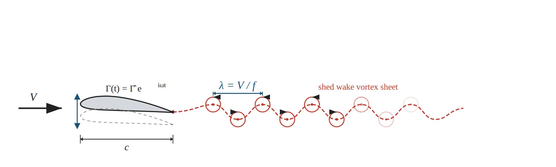
Every time a wing changes its angle of attack, however slightly, it alters its bound circulation. Kelvin’s circulation theorem demands that the total circulation in the flow field remain constant. The wing therefore sheds a vortex of equal and opposite strength into its wake with every incremental change in lift. For a wing oscillating in bending, this process repeats periodically, producing a sheet of vortices trailing downstream at approximately the freestream velocity [1].
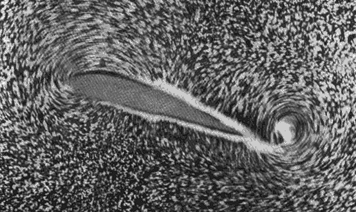
These wake vortices are not passive remnants of past motion. Each vortex element induces a velocity field throughout the flow domain, including at the wing surface, modifying the local angle of attack and therefore the instantaneous pressure distribution. The aerodynamic forces on the wing at any given instant depend not only on the wing’s current position and velocity but on the history of its motion, encoded in the geometry of the trailing vortex sheet. The wake constitutes a memory of the wing’s past.
The question that governs aeroelastic analysis is whether this memory matters. Under what conditions do the shed vortices remain close enough to the wing to produce measurable effects, and when have they been convected so far downstream that their influence is negligible? The answer depends on a single non-dimensional parameter.
The Reduced Frequency
Consider a wing of chord c oscillating at circular frequency ω in a freestream of velocity V. After one full oscillation period T = 2π/ω, the most recently shed vortex has travelled a distance
downstream of the trailing edge. This distance λ is the wavelength of the vortex sheet, the spatial imprint of the oscillation frequency.
The ratio of chord length to this wavelength determines whether the wake vortices remain close enough to influence the wing’s aerodynamics:
where the reduced frequency is defined as [9]:
This is the definition used at RWTH Aachen and in much of the German-language aeroelasticity literature [9]. ω* measures how large the chord is relative to the wake vortex wavelength.
When ω* is small, the chord occupies only a small fraction of λ, the nearest wake vortices are far downstream, and their induced velocity at the wing surface is weak. The aerodynamic forces respond nearly instantaneously, which defines the quasi-steady regime. When ω* grows toward unity and beyond, recently shed vortex elements remain close to the trailing edge, and the flow carries a memory of the wing’s recent past that cannot be ignored [2].
The Anglo-American literature, following Theodorsen [1], uses the semichord b = c/2 as reference length, giving:
The two conventions differ by a factor of two. In what follows, ω* serves as the primary parameter because it connects directly to the ratio c/λ. When evaluating Theodorsen’s function, the conversion k = ω*/2 applies.
The conventional engineering boundary between quasi-steady and unsteady aerodynamics lies at approximately ω* ≈ 0.1 (k ≈ 0.05), corresponding to a vortex wavelength of about ten chord lengths [2], [4].
Theodorsen’s Function: Quantifying the Wake Effect
Theodore Theodorsen solved the problem of an oscillating thin airfoil in incompressible flow in his 1935 NACA report [1]. His solution separates the aerodynamic forces into a non-circulatory component, which arises from the acceleration of fluid mass around the airfoil and responds instantaneously without wake interaction, and a circulatory component, which accounts for the bound circulation required to satisfy the Kutta condition and which is affected by the shed wake.
Theodorsen showed that the circulatory lift can be expressed as the quasi-steady circulatory lift multiplied by a complex-valued transfer function:
where H₀⁽²⁾ and H₁⁽²⁾ are Hankel functions of the second kind, expressible through Bessel functions as Hₙ⁽²⁾(k) = Jₙ(k) − iYₙ(k). The argument is Theodorsen’s k = ω*/2 [1], [2], [3].
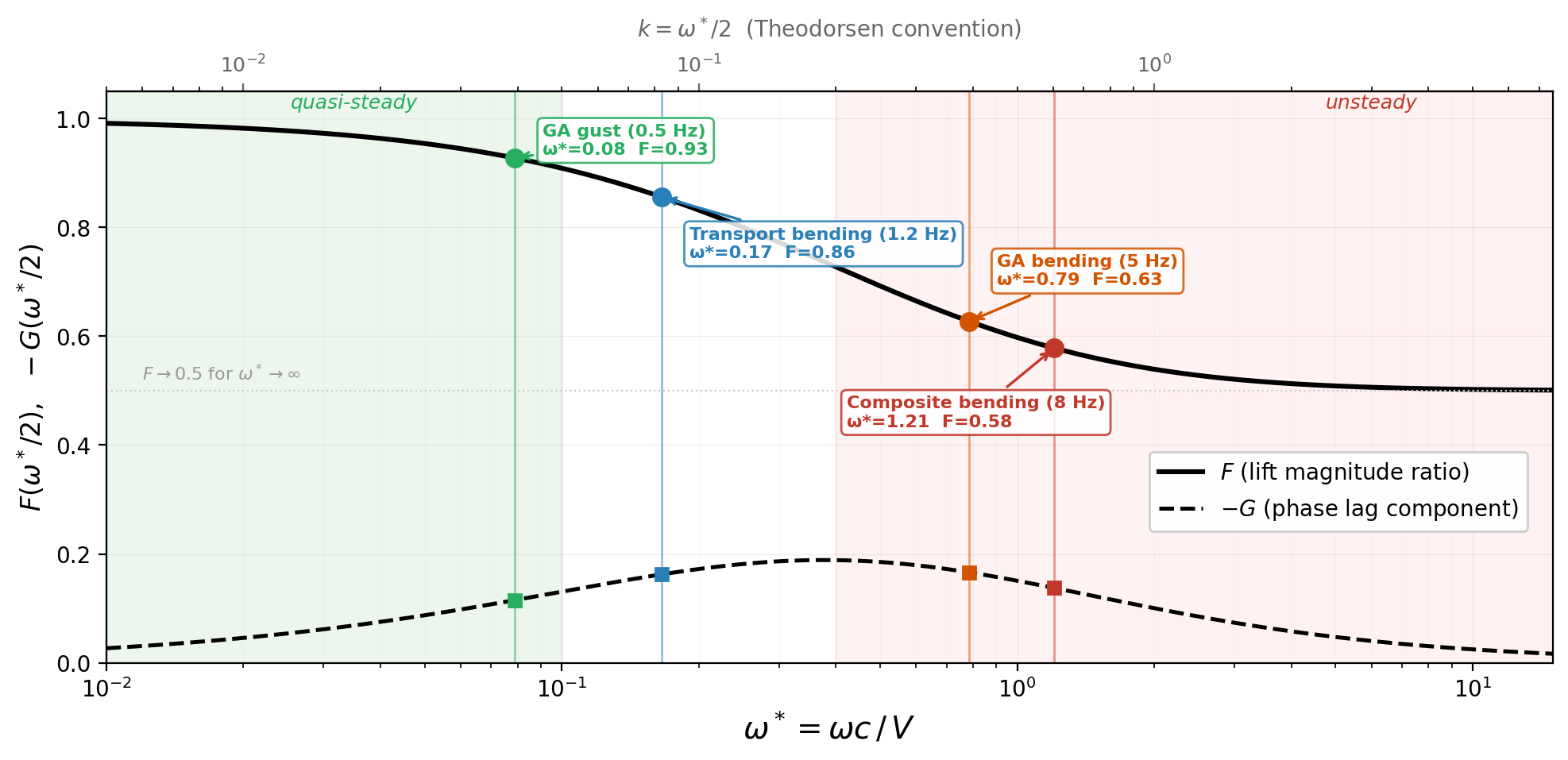
The function C(k) = F(k) + iG(k) splits into real and imaginary parts. The real part F(k) represents the fraction of quasi-steady circulatory lift that survives wake attenuation, which equals 1.0 at k = 0 and decreases monotonically toward 0.5 as k → ∞. The imaginary part G(k) represents the phase lag between wing motion and aerodynamic response, which is negative for all k > 0, reaches a minimum around k ≈ 0.2, and returns toward zero at very large k [1], [3].
When Are Real Wings Affected?
Whether unsteady effects matter reduces to comparing λ to c, but the answer depends as much on the phenomenon as on the aircraft. The same wing can be quasi-steady for one problem and deeply unsteady for another.
Consider a general aviation aircraft with a chord of 1.5 m cruising at 60 m/s. If it encounters atmospheric turbulence at a dominant gust frequency of 0.5 Hz, the resulting wake wavelength is λ = 120 m, roughly eighty chord lengths. The reduced frequency ω* = 0.08 places the problem safely in the quasi-steady regime, and Theodorsen’s function confirms it: F ≈ 0.96, meaning circulatory lift is attenuated by barely four percent.
Now keep the same aircraft but ask about its first wing bending mode at 5 Hz. The wavelength shrinks to λ = 12 m, only eight chord lengths, and ω* jumps to 0.79. Theodorsen gives F ≈ 0.63 and G ≈ −0.11, which translates to 37 percent lift attenuation and a phase lag of roughly ten degrees between wing motion and aerodynamic response. For flutter analysis, where the coupling between bending and torsion depends on both magnitude and phase of the aerodynamic forces, ignoring this produces wrong predictions.
A large transport aircraft with its 5.5 m mean chord and 250 m/s cruise speed might seem like a candidate for quasi-steady treatment. For the first symmetric wing bending mode at 1.2 Hz, λ ≈ 208 m and ω* = 0.17, which gives F ≈ 0.85 and G ≈ −0.08. The fifteen percent attenuation is enough to shift the predicted flutter speed by several percent, which matters given the margins specified in CS-25.629 [5]. And the picture changes for higher modes: torsion frequencies of 8 to 12 Hz push ω* to 0.4–1.0, where unsteady effects dominate.
The most demanding case belongs to the lightweight composite aircraft increasingly common in new CS-23 programmes. A chord of 1.2 m, a cruise speed of 50 m/s, and a first bending frequency of 8 Hz produce λ = 6.25 m, barely five chord lengths, and ω* = 1.2. Theodorsen gives F ≈ 0.57: nearly half the circulatory lift has been attenuated by the wake. For certification under CS-23 Amendment 5, which requires freedom from flutter up to 1.2 V_D [5], an incorrect aerodynamic model can lead to either unnecessary structural reinforcement or an unsafe design.
Modern aircraft design is moving toward configurations that push reduced frequencies upward. The pursuit of aerodynamic efficiency drives designers toward high-aspect-ratio planforms with correspondingly small chords, which directly increases ω* = ωc/V. Composite structures, while lighter than their metallic equivalents, tend to be more flexible in both bending and torsion, which can raise the structural eigenfrequencies that enter the numerator. And the operational speeds of new CS-23 aircraft remain moderate, so the velocity in the denominator does not compensate.
The trend is visible across generations of GA aircraft. The aluminium trainers that defined the category for half a century, for example the Cessna 152 or Cessna 172, have mean chords around 1.47 m at aspect ratios below 7.5. The Piper Malibu, designed for aerodynamic efficiency rather than manufacturing simplicity, already had an aspect ratio of 10.5 and a mean chord of 1.24 m in 1983. Modern composite designs continue this trajectory: the Diamond DA40 at c̄ = 1.13 m, the Pipistrel Velis Electro at c̄ = 0.89 m and AR = 12.1.
Sailplane designers have been living with these parameters for decades. The ASW-19, a 15 m design with 10 m² wing area, has a mean chord of 0.67 m. The AS 33, a few generations later, brings it down to 0.59 m at 15 m span and 0.56 m at 18 m span. Combined with soaring speeds of 40 to 60 m/s and the flexible composite structures standard in the class, these aircraft routinely operate at reduced frequencies where unsteady effects cannot be neglected. Whether and how quickly powered aircraft follow them further into that territory depends on how far designers push aspect ratio and structural flexibility in pursuit of efficiency.
The certification implications extend beyond flutter. Gust response analysis under CS-23.341 and CS-25.341 depends on the Küssner function for sharp-edged gust response and the Wagner function for indicial lift response, both related to the Theodorsen function through Fourier transform relationships [2], [8]. All three arise from the same physical origin: the influence of shed wake vorticity on the instantaneous aerodynamic forces acting on the wing.
Classification and Computational Context
The reduced frequency fits into Collar’s 1946 triangle of aeroelastic interactions between aerodynamic, elastic, and inertial forces [2], [9]. Dynamic aeroelastic phenomena, which include flutter, gust response, and aeroservoelastic coupling, occupy the region where all three force systems interact, and ω* determines which aerodynamic model is appropriate.
Theodorsen's 1935 analysis [1] remains the analytical foundation, extended to three-dimensional configurations through the doublet lattice method (Albano and Rodden, 1969) as implemented in MSC Nastran's SOL 145 [4]. These methods compute aerodynamic influence matrices as a function of reduced frequency, and the computational cost grows with ω*: at low k, a handful of frequency points suffice to capture the aerodynamic transfer function, while the regime above k = 0.3 demands progressively denser sampling. Where the assumptions of potential flow break down, whether at high angles of attack, in transonic flow, or with separated boundary layers, unsteady RANS or LES methods offer higher fidelity, but at a cost that scales steeply with both the reduced frequency and the geometric complexity of the configuration [6], [7].
The reduced frequency is the first quantity a structural dynamics engineer should calculate when beginning an aeroelastic analysis. It determines the analytical framework required.
For the current generation of lightweight composite aircraft, first wing bending at cruise falls in the range ω* = 0.6–1.2, where Theodorsen predicts the steepest deviation from quasi-steady behaviour. Only for slow phenomena that involve manoeuvre loads, long-wavelength gusts, or rigid-body dynamics does the quasi-steady assumption remain justified. The engineer’s choice, guided by a comparison of wake vortex wavelength to chord, has consequences for the predicted flutter margin and the structural mass required to meet it.
If you find value in Engineering Airworthiness, consider subscribing for free.
If you think someone might benefit from it, feel free to share it.
References
[1] T. Theodorsen, “General Theory of Aerodynamic Instability and the Mechanism of Flutter,” NACA Report 496, 1935.
[2] R. L. Bisplinghoff, H. Ashley, and R. L. Halfman, Aeroelasticity. Cambridge, MA: Addison-Wesley, 1955. Reprinted by Dover Publications, 1996.
[3] Y. C. Fung, An Introduction to the Theory of Aeroelasticity. New York: John Wiley & Sons, 1955. Reprinted by Dover Publications, 1993.
[4] J. R. Wright and J. E. Cooper, Introduction to Aircraft Aeroelasticity and Loads, 2nd ed. Chichester: John Wiley & Sons, 2015.
[5] European Union Aviation Safety Agency, “Certification Specifications and Acceptable Means of Compliance for Normal, Utility, Aerobatic, and Commuter Category Aeroplanes (CS-23),” Amendment 5, 2017.
[6] E. H. Dowell, Ed., A Modern Course in Aeroelasticity, 5th ed. Cham: Springer, 2015.
[7] M. Patil and D. Hodges, “On the importance of aerodynamic and structural geometrical nonlinearities in aeroelastic behavior of high-aspect-ratio wings,” Journal of Fluids and Structures, vol. 19, no. 7, pp. 905–915, 2004.
[8] H. G. Küssner, “Zusammenfassender Bericht über den instationären Auftrieb von Flügeln,” Luftfahrtforschung, vol. 13, no. 12, pp. 410–424, 1936. English translation: NACA TM 979, 1941.
[9] Lecture Notes, “Grundlagen der Aeroelastik,” RWTH Aachen University, 2015.
[10] H. Wagner, “Über die Entstehung des dynamischen Auftriebes von Tragflügeln,” Zeitschrift für Angewandte Mathematik und Mechanik, vol. 5, no. 1, pp. 17–35, 1925.