


The static stability boundary of aircraft structures remains one of the most consequential design constraints in aerospace engineering, yet its underlying mechanism receives far less attention than its dynamic counterpart, flutter. Aeroelastic divergence describes the condition where aerodynamic forces amplify structural deformations in a self-reinforcing loop until catastrophic failure occurs. Unlike flutter, which manifests as oscillatory instability, divergence develops as a monotonically increasing deformation that, once initiated, progresses to destruction within seconds.
The phenomenon first gained systematic attention during the rapid development of high-speed aircraft in the 1930s and 1940s, when designers encountered failures that could not be explained by conventional strength analyses. Wings that possessed adequate structural margins under static loads would twist to destruction at specific flight speeds well below the design dive speed. The recognition that structural flexibility, aerodynamic loading, and flight speed formed a coupled system requiring integrated analysis fundamentally changed how engineers approached aircraft structural design.
Modern certification specifications mandate comprehensive divergence analyses for all aircraft configurations. The critical divergence speed must exceed the design dive speed VD by a prescribed margin, typically 15 percent for certification under normal category regulations. Understanding the physical mechanism, the mathematical formulation, and the practical implications of divergence remains essential for anyone involved in aircraft structural design, certification, or flight testing.
The Physical Mechanism
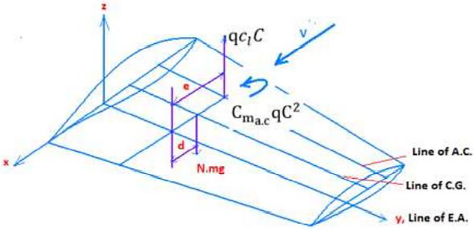
Aeroelastic divergence results from the coupling between aerodynamic moments and structural torsion. Consider a wing section at a given spanwise station subjected to a steady airflow. The aerodynamic forces generate a moment about the wing’s elastic axis, which we define as the line along which torsional deformations occur without inducing bending. This moment depends on the angle of attack, which includes both the rigged angle and any elastic twist of the wing structure.
When the wing twists nose-up due to aerodynamic loading, the local angle of attack increases, which in turn increases the aerodynamic lift. For a wing section where the elastic axis lies behind the aerodynamic center, this increased lift creates an additional nose-up moment that further increases the twist. The structure resists this deformation through its torsional stiffness, characterized by the product of the torsional rigidity GIt and the rate of twist along the span.
At low flight speeds, the torsional stiffness dominates and the wing reaches an equilibrium position where the elastic restoring moment balances the aerodynamic moment. As flight speed increases, the aerodynamic forces grow quadratically with velocity through the dynamic pressure q=12ρV∞2, while the structural stiffness remains constant. At a critical speed, the aerodynamic moment gradient with respect to twist angle equals the structural stiffness gradient, and the system reaches a neutral equilibrium. Beyond this speed, any small disturbance leads to unbounded growth of the twist angle. This is the divergence condition.
The location of the elastic axis relative to the aerodynamic center determines whether divergence can occur at all. If the elastic axis lies ahead of the aerodynamic center, any nose-up twist produces a nose-down aerodynamic moment that opposes the deformation. Such a configuration is inherently divergence-free. However, structural considerations typically require placing primary load-carrying spars near the point of maximum airfoil thickness, which often lies behind the aerodynamic center located at approximately 25 percent chord. This structural necessity makes divergence a relevant concern for most conventional aircraft configurations.
Mathematical Formulation
The systematic analysis of torsional divergence begins with the static equilibrium equation for a wing section under combined structural and aerodynamic moments. Consider a simplified two-dimensional model where a wing section of chord l and span b is mounted on a torsionally flexible support with stiffness kα at the elastic axis. The structural restoring moment equals kα times the twist angle Θ.
The aerodynamic lift per unit span follows from strip theory, where the lift curve slope cα′ (typically 5.5 to 6.5 per radian for subsonic airfoils) acts on the total angle of attack including both the rigged angle αs and the elastic twist Θ. The dynamic pressure q grows quadratically with flight speed. The aerodynamic moment about the elastic axis includes contributions from the pitching moment at zero lift and from the lift acting at distance e aft of the elastic axis, where e represents the distance from the elastic axis to the aerodynamic center.
Static equilibrium requires that the structural restoring moment balances the aerodynamic moment. The structural moment equals kα times the twist angle Θ, where kα represents the torsional spring stiffness. Solving this equilibrium condition reveals that the twist angle depends on a denominator term that decreases as dynamic pressure increases. When this denominator reaches zero, the twist angle becomes infinite. This critical condition defines the divergence dynamic pressure:
where kα is the torsional stiffness, cα′ is the lift curve slope, l is the chord length, and e is the distance from elastic axis to aerodynamic center.
Converting to airspeed yields the divergence speed:
This formulation reveals that divergence speed increases with the square root of torsional stiffness and decreases with the square root of the distance from the elastic axis to the aerodynamic center. The air density ρ appears in the denominator, indicating that divergence speed decreases at higher altitudes where the air is less dense.
For a wing of finite span with distributed torsional stiffness, the analysis requires solving a differential equation along the span. The governing equation balances the rate of change of torsional moment with the distributed aerodynamic moment. For a wing with constant properties along the span and extending from root to tip over span b, this yields a second-order differential equation characterized by the parameter λ2.
This parameter scales as the ratio of aerodynamic forcing to structural stiffness:
where GIt represents the torsional rigidity, combining the shear modulus G with the torsional constant It of the wing cross-section.
The solution involves trigonometric functions of λy along the span. Applying boundary conditions of zero twist at the wing root and zero torsional moment at the free tip yields a critical constraint that occurs when λb reaches π2. This condition determines the divergence dynamic pressure for the distributed wing:
The corresponding divergence speed follows as:
This result demonstrates that divergence speed is independent of the rigged angle of attack and the pitching moment coefficient. The speed depends only on structural stiffness properties, geometric parameters, and the lift curve slope. For a given wing planform and airfoil, increasing the torsional rigidity GIt provides the most direct path to higher divergence speed.
Derivative Interpretation and Critical Speed
The divergence condition emerges mathematically from examining when the system’s differential equation transitions from having oscillatory solutions to having solutions that grow without bound. Consider the characteristic equation associated with the governing differential equation. For positive values of the λ2 parameter, the solutions contain sine and cosine terms representing stable equilibrium configurations. The critical point occurs when the boundary conditions force the argument λb to approach π2, at which point the mathematical solution becomes singular.
This singularity manifests physically as the loss of static stability. Below the divergence speed, any imposed twist produces a finite equilibrium deformation. At the divergence speed, an infinitesimal disturbance leads to infinite deformation. Above the divergence speed, no equilibrium exists and the wing twists continuously under aerodynamic loading.
The critical parameter λ scales as the square root of dynamic pressure. The divergence condition λb=π2 therefore establishes a critical dynamic pressure proportional to ²1b². Wings with greater span reach divergence at lower speeds for a given torsional rigidity, which explains why high-aspect-ratio sailplanes require particularly careful attention to torsional stiffness design.
The practical significance of this mathematical result extends beyond calculating a single critical speed. The formulation enables parametric studies examining how variations in structural properties, geometric parameters, and flight conditions affect the divergence boundary. During preliminary design, engineers use this relationship to establish minimum torsional stiffness requirements. During certification, flight test programs verify that the actual aircraft demonstrates adequate margins above the calculated divergence speed.
Factors Influencing Divergence Speed
The primary design parameters affecting divergence speed emerge directly from the governing equations. Torsional rigidity GIt appears in the numerator of the divergence speed expression, providing the most direct means of increasing the critical speed. Structural designers achieve higher torsional rigidity through strategic placement of torsion-resistant structure, typically by locating spars far apart chordwise or by using closed-section torsion boxes. The closed torsion box, consisting of spars, ribs, and attached skin panels forming a closed loop in cross-section, provides exceptional torsional rigidity for a given structural weight.
The geometric parameter e, representing the distance from the elastic axis to the aerodynamic center, appears in the denominator. Reducing this distance by moving the elastic axis rearward toward the aerodynamic center increases divergence speed significantly. However, structural constraints typically limit this freedom. The main spars, which define the elastic axis location, must be placed where the airfoil has sufficient depth to accommodate the required bending strength. For most airfoils, this occurs forward of the 25 percent chord where the aerodynamic center is located.
Wingspan b appears in the denominator through a ²1b² term, indicating that divergence speed decreases rapidly with increasing span. A wing with twice the span requires four times the torsional rigidity to maintain the same divergence speed. This relationship explains why high-aspect-ratio aircraft, from sailplanes to high-altitude research aircraft, demand exceptional attention to torsional stiffness. The Global Hawk, with its 35-meter span and exceptionally slender wing, employs a substantial torsion box with composite construction to achieve adequate divergence margins.
The lift curve slope c′α depends primarily on the airfoil characteristics and the flow regime. In subsonic flow, typical values range from 5.5 to 6.5 per radian. At transonic speeds, compressibility effects can increase the effective lift curve slope, reducing divergence speed. Supercritical airfoils, designed to delay the onset of compressibility effects, help maintain lower effective lift curve slopes at high subsonic speeds.
Air density ρ appears in the denominator of the velocity expression, meaning that divergence speed decreases as density decreases. An aircraft that demonstrates adequate divergence margin at sea level on a standard day will have reduced margin at high altitudes or on hot days. Flight test programs must verify divergence margins across the entire flight envelope, including the highest altitude and lowest density conditions where the aircraft will operate.
Design Implications and Certification Requirements
The requirement that divergence speed must exceed the design dive speed VD by a specified margin drives structural design decisions from the earliest stages of aircraft development. For normal category aircraft, EASA CS-23.629 requires that divergence not occur at speeds up to VD, which itself is typically 1.4 times the maximum level flight speed in the cruise configuration. This effectively requires that divergence speed exceed 1.4 times cruise speed.
During preliminary design, engineers establish the required torsional rigidity by working backward from the speed requirement. For a given wing planform, airfoil, and spar arrangement, the calculation determines the minimum torsional constant It of the wing cross-section. This requirement then influences detail design decisions including skin thickness, spar cap sizing, and rib spacing. Composite construction offers advantages here, as designers can tailor fiber orientations to maximize torsional rigidity with minimal weight penalty.
The forward location of the elastic axis relative to the wing’s structural centroid creates a coupling between bending and torsion that must be considered in the complete aeroelastic analysis. Composite wings with forward-swept planforms can exploit this coupling to create wash-out under load, where the wing twists nose-down as it bends upward. This beneficial coupling increases the effective divergence speed. Conversely, aft sweep creates wash-in coupling that reduces divergence speed and must be compensated by increased structural stiffness.
Flight testing to demonstrate divergence margin follows standardized procedures outlined in the certification basis. Test pilots explore the flight envelope systematically, monitoring wing twist angles through photogrammetric measurements or strain gauge data. The test program must demonstrate that structural deformations remain bounded and that the aircraft exhibits positive stability margins throughout the approved flight envelope. For aircraft with fly-by-wire controls and active load alleviation systems, the divergence analysis must account for the control system response characteristics.
Certification authorities require comprehensive documentation of the divergence analysis, including the structural model, aerodynamic model, and comparison of calculated divergence speed to flight test results. The structural model must capture the torsional stiffness distribution along the span with sufficient fidelity. Modern finite element analyses typically employ beam elements with six degrees of freedom at each node, allowing coupled bending-torsion analysis. The aerodynamic model must represent the lift distribution and pitching moment characteristics across the operational Mach number range.
Practical Examples and Historical Context
The Junkers Ju 287, first flown in August 1944, demonstrated both the promise and the challenges of forward-swept wing design. German engineer Hans Wocke recognized that forward sweep offered advantages for a jet bomber, including better lift distribution at low speeds and the ability to place the weapons bay at the optimal location without interference from wing spars. However, the configuration encountered severe aeroelastic divergence problems during high-speed testing.
During flight tests at Brandis, the Ju 287 V1 reached 660 kilometers per hour in dives, confirming the predicted aeroelastic issues. Test pilots reported decreasing elevator forces during tight turns and pull-outs from shallow dives, clear indications of divergence effects. The structural modifications required to prevent divergence using conventional aluminum construction would have resulted in prohibitive weight penalties. The V1 prototype retained fixed landing gear partly because incorporating retractable gear bays would have required cutouts in the wing torsion box, further reducing the torsional stiffness needed to resist divergence.
Four decades later, the Grumman X-29 demonstrated that composite materials could solve the divergence problem that had defeated the Ju 287. The X-29’s forward-swept wings, swept at 29.3 degrees, employed graphite-epoxy composite construction with fiber orientations specifically tailored to control aeroelastic behavior. Rather than simply building a stiffer wing, which would carry excessive weight, the design exploited anisotropic elastic coupling between bending and torsion inherent in composite laminates.

As aerodynamic lift forces the wing tips to bend upward, the composite layup orientation causes the wing to twist nose-down, counteracting the divergence tendency of the forward-swept planform. The X-29 program, which flew 242 research flights from 1984 to 1991, successfully demonstrated that aeroelastic tailoring could eliminate structural divergence within the flight envelope. The aircraft maintained controllability up to 67 degrees angle of attack, validating the forward-swept wing concept when combined with appropriate materials and structural design.
Relationship to Control Effectiveness
Aeroelastic divergence represents one point on a spectrum of aeroelastic phenomena affecting control authority. As flight speed increases, the wing’s elastic deformation under aerodynamic loads modifies the effective control surface deflection. For an aileron located on a wing that twists under load, the applied aileron deflection creates not only the intended rolling moment but also induces wing twist that partially counters the effect.
At low speeds, the rigid-body control authority dominates and the aircraft responds as if the structure were perfectly stiff. As speed increases, the elastic effects grow. At the reversal speed VR, the elastic and rigid-body effects exactly cancel, and the control produces zero net effect. Above the reversal speed, the control produces a response opposite to the intended direction. The divergence speed VD represents the ultimate limit where the wing structure cannot support the aerodynamic loads regardless of control input.
The relationship between reversal speed and divergence speed depends on the specific design parameters of the wing and control surface installation. Torsional stiffness, the distance between the elastic axis and the aerodynamic center, control surface size and location, and wing sweep all influence where these critical speeds occur relative to each other. Some aircraft designs result in reversal speeds that exceed divergence speed, while others experience reversal at lower speeds, potentially even within the operational flight envelope. The Boeing 747, for example, deactivates its outboard ailerons at high speeds and relies on inboard ailerons and spoilers to avoid reversal effects. Both phenomena must be evaluated during certification, with requirements that reversal not occur below 1.2 times the design dive speed.
Looking Forward
Modern aircraft increasingly employ active control systems that can modify the aeroelastic response characteristics. By commanding control surface deflections that oppose the aerodynamic moments causing wing twist, these systems effectively increase the apparent structural stiffness and raise the divergence speed. The Airbus A380’s gust load alleviation system, while primarily designed to reduce fatigue loads, provides a secondary benefit of improved divergence margin by reducing the maximum twist angles experienced during maneuvers.
External installations such as engine pylons, fuel tanks, and sponsons introduce additional considerations for divergence analysis. These installations modify both the mass distribution and the aerodynamic loading along the span. Engine nacelles mounted on pylons create local concentrations of mass that affect the elastic axis location and introduce coupling between bending and torsion. The aerodynamic forces on engine installations and drop tanks can either stabilize or destabilize the wing depending on their position relative to the elastic axis. Seaplane sponsons, which serve as auxiliary buoyancy devices, similarly affect the wing’s aeroelastic behavior through both their mass and their aerodynamic influence. Each configuration change requires careful analysis throughout the flight envelope to ensure adequate divergence margins are maintained.
The ongoing development of morphing wing structures, which change camber and twist through active control, blurs the traditional boundary between rigid structure and active control. These configurations require redefining the divergence analysis to account for commanded structural deformations distinct from elastic deformations under aerodynamic load. The certification basis for such aircraft remains under development, but the fundamental requirement remains: the structure must maintain positive static stability throughout the operating envelope.
If you find value in Engineering Airworthiness, consider subscribing for free.
If you think someone might benefit from it, feel free to share it.
Update (December 8, 2025): The section “Relationship to Control Effectiveness” has been revised based on reader feedback. The original text made general statements about the relationship between reversal speed and divergence speed for conventional versus tailless configurations. Reader Lyssandre Rammos correctly pointed out that this relationship is not universal but depends on specific design parameters including torsional stiffness, elastic axis location, control surface geometry, and wing sweep. The revised text now accurately reflects that the relative magnitudes of these speeds are design-dependent rather than configuration-dependent. The Boeing 747 example illustrates how reversal can occur within the operational envelope for some designs, requiring operational solutions such as deactivating outboard ailerons at high speeds. Thanks to the readers who identified this oversimplification in the original formulation.