

The Generalized Approach Parameter
Milwitzky’s Framework for Seaplane Impact Similarity

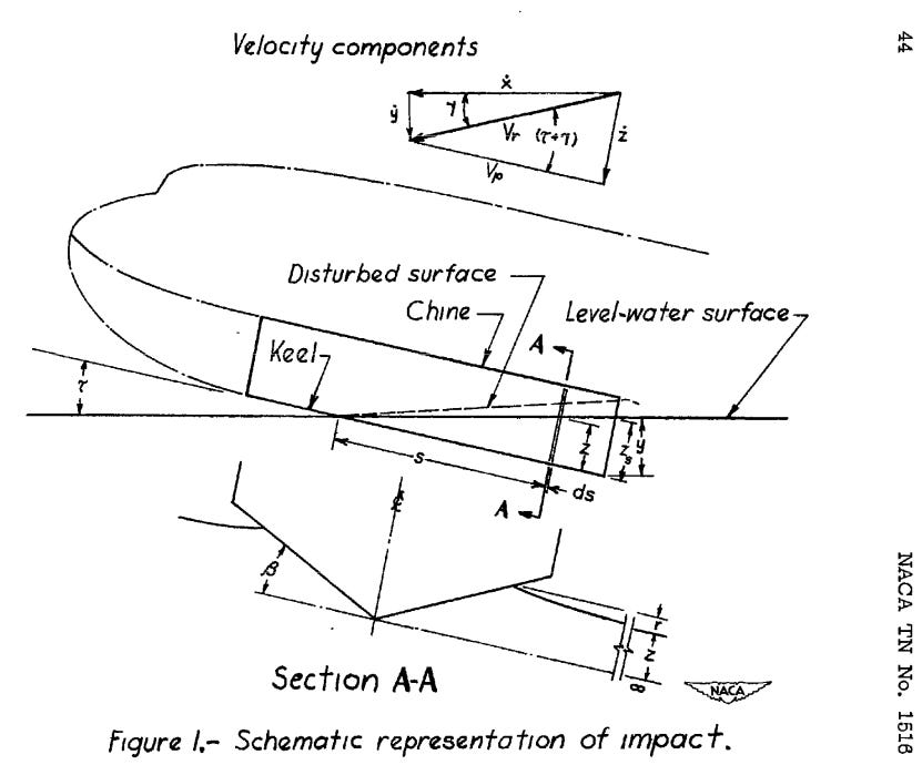
Wagner’s 1932 theory provides accurate pressure distributions and forces for water impact at a given instant. Yet calculating the complete time history of accelerations during a seaplane landing requires solving a more complex problem. The aircraft does not merely impact at constant velocity. It decelerates as hydrodynamic forces build, and this deceleration affects the forces themselves through the time-varying virtual mass. The differential equation governing this coupled motion contains five independent parameters: flight path angle, effective trim angle, deadrise angle, the ratio of water density to aircraft mass, and touchdown velocity.
Five parameters do not seem excessive for numerical integration. A modern computer evaluates the differential equation in milliseconds. Yet the value of Milwitzky’s generalization, developed in NACA TN 1516 (1948) and presented comprehensively in NACA Report 1103 (1952), lies not primarily in computational savings but in physical insight.
The generalized approach parameter reveals which combinations of landing conditions produce equivalent impact behavior. A steep approach at high trim angle can yield the same dimensionless response as a shallow approach at low trim angle if both produce identical values of the approach parameter. This equivalence remains invisible when solving the dimensional equations directly. Two engineers analyzing different aircraft under different conditions might obtain numerically identical acceleration histories without recognizing that their problems share the same underlying physics.
Dimensional analysis in fluid mechanics follows this pattern. Reynolds number does not merely save computation. It reveals that a small pipe at high velocity behaves identically to a large pipe at low velocity when their Reynolds numbers match. The insight enables scaling from model tests to full-scale predictions and identifies the governing physics independent of absolute dimensions. Milwitzky’s approach parameter provides analogous capability for seaplane impact analysis, identifying which parameter combinations produce dynamically similar landings regardless of aircraft size or specific flight conditions. The analogy holds in spirit rather than in strict similarity theory sense, since the approach parameter emerges from the specific structure of the impact equations rather than from pure dimensional considerations.
Definition of the Approach Parameter
Milwitzky combined the initial flight path angle and the effective trim angle into a single dimensionless quantity. Following the notation of NACA Report 1103, the approach parameter is defined as follows.
Here τ represents the trim angle at the instant of contact, while the flight path angle γ₀ measured from horizontal describes the approach trajectory. The trigonometric combination captures how the geometry of water entry depends on both the hull attitude and the descent path.
The parameter spans a continuous range with physically meaningful boundaries. For vertical impact where the resultant velocity is normal to the keel (γ₀ = 90° - τ), the approach parameter takes its minimum value.
This expression follows from substituting γ₀ = 90° - τ into the definition and represents the most severe impact case where all kinetic energy must be dissipated through hydrodynamic forces acting perpendicular to the water surface. The vertical impact condition lies at the boundary of the theory’s original validation range, though the limiting value still provides useful guidance. At the opposite extreme, pure glide conditions with zero flight path angle push the approach parameter toward infinity. In this limit the aircraft skims along the surface without significant penetration, and the impact phase gives way to steady planing.
Report 1103 indicates that the practical range of the approach parameter for conventional seaplanes lies between K = 0.2 and K = 10. A typical seaplane landing in smooth water at 6° trim with vertical velocity of 3 feet per second and horizontal velocity of 80 miles per hour corresponds to K ≈ 4. Higher speed landings at 150 miles per hour with the same vertical velocity yield K ≈ 7.6. Landing into the flank of an oncoming wave might produce values as low as K = 0.2.
The Generalized Variables and Governing Equations
To complete the generalization, Milwitzky introduced dimensionless variables that reduce the equations of motion to a universal form. The generalized displacement u, generalized velocity u’, generalized acceleration u’‘, and generalized time σ relate to dimensional quantities through scaling factors that incorporate the deadrise angle function, aspect ratio correction, water density, aircraft mass, and trim angle.
The scaling between dimensional penetration and generalized displacement takes the form
where Γ combines the geometric and inertial parameters. The specific form of Γ depends on the definitions of the virtual mass function ε(β) and aspect ratio correction φ(A), which Report 1103 discusses in detail. Wagner’s iterative solution for the virtual mass leads to the deadrise function
while Pabst’s empirical aspect ratio correction gives
With these definitions, the motion satisfies the following differential equation that depends only on the generalized variables and the approach parameter K.
This is equation (15) from Report 1103 and represents the fundamental equation of motion in generalized form. The term (1 + u³) reflects the growing virtual mass during penetration, since u³ equals the ratio of virtual mass to aircraft mass at any instant. The quadratic term in (u’ + K) captures how both the instantaneous velocity and the approach geometry influence the hydrodynamic force.
Integration of this equation yields the relationship between generalized displacement and velocity throughout the impact.
This integrated form, equation (17) in Report 1103, permits determination of displacement for any given velocity without requiring numerical integration. The exponential structure and rational functions create a nonlinear relationship that cannot be inverted analytically, but the solution depends only on the single parameter K once appropriate initial conditions are specified. This represents a dramatic simplification from the original formulation where aircraft mass, water density, deadrise angle, trim angle, flight path angle, and touchdown velocity all appeared as independent variables.
What Each Component Contributes
The approach parameter structure reveals how different landing conditions affect impact severity through specific mechanisms.
Effect of Flight Path Angle
The flight path angle appears in the denominator through the sine function. Steeper approaches with larger flight path angles decrease the approach parameter, moving toward the limiting value that corresponds to vertical impact. This regime generates the highest peak accelerations because the aircraft must rapidly arrest its vertical motion through hydrodynamic forces alone. Shallow approaches with small flight path angles increase K, producing gentler impacts where horizontal velocity carries the aircraft forward while gradual penetration develops hydrodynamic lift.
The cosine term in the denominator introduces coupling between flight path and trim angles. At steep approach angles near 90°, this factor approaches zero and the approach parameter grows rapidly. Physical interpretation suggests this corresponds to conditions where the hull rapidly transitions from impact to planing as it converts vertical momentum into horizontal motion.
Effect of Trim Angle
The trim angle contributes through the numerator sine function. Increasing trim angle at constant flight path angle increases the approach parameter, generally reducing impact severity. Higher trim presents a larger projected area to the oncoming water, developing hydrodynamic forces earlier in the penetration sequence before peak pressures build.
This effect has limits, however. Very high trim angles approach the stall condition in air and create their own problems including excessive drag and potential loss of control. The trim angles that minimize impact loads may not coincide with those that provide adequate flying qualities during the flare. Seaplane pilots typically land at trim angles between 6° and 12°, representing a practical compromise between impact load reduction and aircraft controllability.
Combined Geometric Sensitivity
The approach parameter exhibits different sensitivities to its constituent angles depending on the operating regime. Near vertical impact, small changes in flight path angle produce large changes in K because the sine function varies most rapidly near zero argument. Conversely, at shallow approach angles typical of normal landings, the approach parameter becomes more sensitive to trim angle variations.
This behavior has practical implications for flight testing. Measurements at very shallow approach angles require precise determination of the flight path to accurately characterize the approach parameter. At steeper angles that might occur during rough water operations or emergency landings, trim angle measurement becomes the critical factor for correlation with theoretical predictions.
The Scaling Factor and Its Physical Meaning
The scaling factor Γ that normalizes penetration depth deserves separate examination because it reveals how aircraft and hull geometry interact to determine impact dynamics.
Deadrise Angle Influence
The factor involving deadrise angle originates from Wagner’s formulation of virtual mass.
For typical seaplane deadrise angles between 15° and 30°, this factor varies by roughly a factor of four. Shallower deadrise angles increase the factor, meaning that lower deadrise hulls develop virtual mass more rapidly during penetration. This manifests as higher accelerations for a given sink rate because the fluid must accelerate more violently to flow around the hull.
The physical mechanism involves the rate at which wetted width spreads laterally. Shallow deadrise sections present a larger horizontal extent per unit of vertical penetration, capturing and accelerating more water mass in a shorter time. Deep-V hulls allow water to escape more gradually along the inclined surface, developing forces progressively rather than impulsively.
This explains why rough water amphibians typically employ 20° to 25° deadrise despite the weight penalty associated with deeper hulls. The reduced impact loads permit lighter structure even though the hull volume increases. Conversely, racing hydroplanes with extremely shallow deadrise achieve low drag but require structural design for severe impact loads.
Mass Ratio and Beam Loading
The density ratio appearing in the scaling determines how significant added mass effects become.
This ratio alone does not tell the complete story, however. The virtual mass grows during penetration and reaches its maximum when the chine immerses. Understanding when virtual mass dominates requires examining what controls that maximum value.
The virtual mass at chine immersion scales with the wetted dimensions.
The ratio of maximum added mass to aircraft mass then becomes the following.
The first factor is the inverse of beam loading W/b³, which appears in CS-23.527 as the governing parameter for regulatory load estimation. The second factor is the hull slenderness ratio. Together they determine whether virtual mass remains a correction or becomes the dominant term in effective inertia.
Beam loading has units of density and carries direct physical meaning. It compares aircraft weight to a characteristic water volume defined by the beam cubed. Low beam loading means the hull displaces substantial water volume relative to aircraft mass. High beam loading means the aircraft carries much mass relative to the water volume its hull can engage.
A light amphibian with a broad hull optimized for stability exhibits low beam loading. When such an aircraft impacts water, the virtual mass grows rapidly with penetration and can approach or exceed the aircraft mass before chine immersion. The effective inertia changes dramatically during the impact event, nearly doubling from initial contact to maximum penetration. This time-varying inertia produces acceleration histories that differ markedly from what constant-mass analysis would predict. Milwitzky’s generalized formulation captures this behavior through the (1 + u³) term in the differential equation, where the cubic dependence reflects how added mass accumulates with penetration.
A heavy aircraft with a slender hull designed for cruise efficiency exhibits high beam loading. The virtual mass still grows during penetration, but it remains a modest fraction of aircraft mass throughout the impact. The effective inertia increases perhaps 20% to 40% rather than doubling. Simpler analysis methods that treat added mass as a fixed correction factor can provide adequate accuracy for preliminary sizing because the time variation of effective mass matters less when that variation stays within a narrower band.
This distinction does not correlate directly with aircraft size. A Cessna 172 on amphibious floats and a Lake LA-4 have similar gross weights around 1,100 kg to 1,200 kg, yet their beam loading values differ substantially because their hull geometries reflect different design priorities. The Lake’s purpose-built flying boat hull has generous beam for water stability, yielding low beam loading and pronounced virtual mass effects. The Cessna’s floats represent a compromise that preserves land performance, resulting in higher beam loading and more moderate added mass contributions.
Large flying boats historically featured relatively slender hulls with high length-to-beam ratios that kept beam loading elevated despite their size. The Grumman HU-16 Albatross at 17,000 kg landing mass with a beam around 2.8 meters exhibits beam loading comparable to much smaller aircraft with proportionally narrower hulls. Modern electric seaplane designs often push toward broader hulls to accommodate battery volumes, which reduces beam loading and increases the importance of accurate virtual mass modeling regardless of the absolute aircraft size.
The practical implication for analysis method selection follows from beam loading rather than from aircraft category. When beam loading falls below roughly 100 kg/m³, virtual mass effects dominate the impact dynamics and the full coupled formulation becomes necessary for accurate predictions. Above 200 kg/m³, simplified methods that apply fixed added mass corrections often provide acceptable accuracy for preliminary work. Between these bounds, engineering judgment must weigh the accuracy requirements against analysis effort.
Trim Angle in the Scaling
The scaling factor Γ retains explicit dependence on trim angle through trigonometric terms that adjust for the projection of hydrodynamic forces. This means the differential equation is not fully generalized because changes in the approach parameter K through trim angle variation simultaneously alter the coordinate scaling. The generalization succeeds in reducing the number of parameters but does not achieve complete universality.
Report 1103 acknowledges this limitation explicitly. Numerical studies show that this residual dependence introduces errors of 10% to 15% when interpolating between solutions at different trim angles using only the approach parameter. For preliminary sizing this accuracy often suffices, but detailed certification analysis may require direct integration at the specific conditions of interest rather than reliance on generalized charts.
Limitations of the Generalized Formulation
Milwitzky’s approach provides a powerful simplification but rests on specific assumptions that bound its applicability.
The Incomplete Generalization
As noted above, the scaling factor Γ still depends explicitly on the effective trim angle. Report 1103 discusses this limitation and presents charts showing the influence of trim on the generalized variables. For most practical applications within the normal landing envelope, this residual dependence remains acceptably small.
Constant Section Assumption
The formulation assumes prismatic hull sections that maintain constant deadrise along the impact zone. Real seaplane hulls incorporate variable deadrise that typically decreases from bow to step, creating load distributions that differ from the theoretical predictions.
Strip theory approaches can extend the method to variable geometry by treating each station independently and integrating the local contributions. This requires additional bookkeeping but preserves the conceptual framework of generalized solutions applied at each section.
Rigid Body Limitation
Both Wagner’s underlying theory and Milwitzky’s generalization treat the aircraft as rigid. Real structures deform under hydrodynamic loading, and this deformation alters the pressure field through the mechanism Meyerhoff identified in his 1965 hydroelastic coupling analysis.
For stiff aluminum construction the rigid body assumption introduces errors typically below 10%. Modern composite hulls with tailored stiffness distributions may exhibit significantly larger deviations, requiring coupled fluid-structure analysis that lies beyond the scope of classical impact theory.
Validity Range for Angles
The theory was developed and validated primarily for the range of angles encountered in normal seaplane operations. Flight path angles beyond 15° and trim angles above 15° push against the limits of the original experimental validation, though the equations themselves contain no explicit small-angle approximations.
The vertical impact condition (γ₀ = 90° - τ, corresponding to K = K_min) represents a genuine boundary case. Report 1103 treats this as a limiting condition where momentum conservation takes a special form. For K = 0, the momentum lost by the seaplane equals the momentum gained by the virtual mass directly beneath the keel, with no transfer to the downwash. This produces infinite penetration in the theoretical limit, though buoyancy forces neglected in the theory would bound actual behavior.
Experimental Validation
NACA’s extensive testing program provided validation data across the parameter range typical of operational seaplanes. Steiner’s 1949 comparison in NACA TN 1781 showed that Milwitzky’s generalized theory predicted peak accelerations in fair agreement with measurements for normal landing conditions, generally within the limits of experimental accuracy.
Report 1103 presents comparisons between theoretical and experimental time histories for hull models with 22½°, 30°, and 40° deadrise angles across a range of contact conditions extending from shallow flight paths (K = 10) to extremely steep approaches (K = 0.5). The agreement throughout almost the entire immersion process is described as fairly good.
The theory systematically overpredicted initial accelerations during the first milliseconds of contact while underpredicting the secondary acceleration peak that occurs after maximum penetration. This pattern suggests that the virtual mass formulation captures the integrated behavior correctly but distributes it differently over time than actual impacts exhibit.
For structural design purposes where peak loads determine requirements, the overprediction tendency provides conservative margins. The slight unconservatism in secondary peaks rarely matters because primary impact loads dominate the structural sizing case.
Practical Application
The generalized approach parameter enables rapid assessment of landing load sensitivity to operational variables. A designer can quickly evaluate how much steeper approach paths increase peak accelerations by computing the approach parameter at different flight path angles and consulting the normalized acceleration curves presented in Report 1103.
This proves particularly valuable during preliminary design when hull geometry remains fluid. Deadrise angle trades against structural weight and hydrodynamic drag, with impact loads providing one constraint among several. The ability to estimate acceleration changes from geometry changes without repeated numerical integration accelerates the design iteration cycle substantially.
Certification programs benefit from the framework when establishing the envelope of conditions requiring demonstration. The approach parameter identifies which combinations of approach angle and trim angle produce the most severe loads, guiding selection of critical test points. Rather than exploring the full two-dimensional parameter space, testing can focus on the contours of constant approach parameter that represent equivalent severity.
The generalized charts in Report 1103 show relationships between the motion variables during impact, variations with K at particular stages such as maximum acceleration and maximum penetration, and effects of chine immersion due to increased beam loading. These remain useful references for seaplane design nearly seventy years after publication, a testament to the enduring value of proper dimensional analysis applied to complex physical phenomena.
If you find value in Engineering Airworthiness, consider subscribing for free.
If you think someone might benefit from it, feel free to share it.
References
Milwitzky, B. (1952). “Generalized Theory for Seaplane Impact.” NACA Report 1103. [Primary source for the generalized formulation]
Milwitzky, B. (1948). “A Generalized Theoretical and Experimental Investigation of the Motions and Hydrodynamic Loads Experienced by V-Bottom Seaplanes During Step-Landing Impacts.” NACA TN 1516
Milwitzky, B. (1948). “A Generalized Theoretical Investigation of the Hydrodynamic Pitching Moments Experienced by V-Bottom Seaplanes During Step-Landing Impacts and Comparisons With Experiment.” NACA TN 1630
Steiner, M.F. (1949). “Comparison of Over-All Impact Loads Obtained During Seaplane Landing Tests With Loads Predicted by Hydrodynamic Theory.” NACA TN 1781
Wagner, H. (1932). “Über Stoß- und Gleitvorgänge an der Oberfläche von Flüssigkeiten.” ZAMM, Bd. 12, Heft 4, pp. 193-215
Mayo, W.L. (1945). “Analysis and Modification of Theory for Impact of Seaplanes on Water.” NACA Report 810
Meyerhoff, W.K. (1965). “Die Berechnung hydroelastischer Stöße.” Schiffstechnik, Bd. 12, Heft 60