


Every seaplane hull is two hulls joined at the step. The forebody planes on the water and generates the hydrodynamic lift that carries the aircraft through the takeoff run. The afterbody, in theory, does nothing. It hangs behind the step, ventilated by the air that rushes into the cavity, and waits for the aircraft to fly. This division of labour has defined flying boat design since the 1930s, and the analytical methods we use today, from Savitsky’s planing equations to the simplified load formulae in CS-23, assume it.
The arrangement works. It is well understood, analytically tractable, and backed by decades of operational experience. But it comes with three penalties that grow more significant as performance requirements increase. The step itself is an aerodynamic discontinuity that adds drag in cruise flight. The abrupt transition from wet forebody to dry afterbody concentrates all hydrodynamic forces on a short lever arm ahead of the centre of gravity, which limits the stable trim range and creates the porpoising boundaries that constrain every takeoff. And the hump resistance, which determines whether the aircraft can accelerate through the critical transition from displacement to planing, is higher than it needs to be because the forebody alone must carry the entire hydrodynamic load during this phase.
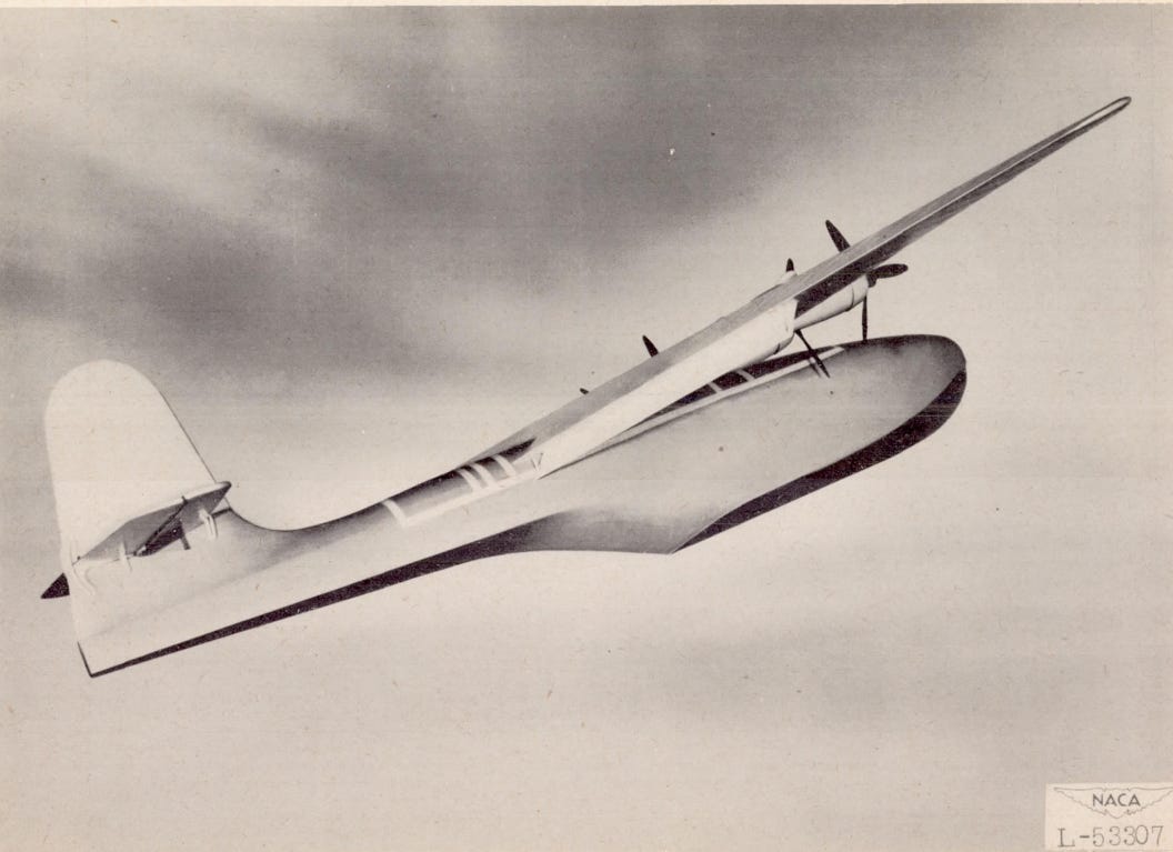
These penalties are accepted because the alternative was never developed to production readiness. Between 1943 and 1956, NACA tested a series of hulls in which the afterbody was not passive. Instead of pulling away from the water behind a sharp transverse step, the afterbody retained a hydrodynamically shaped bottom surface that generated lift at planing speeds. NACA called this configuration a planing tail. The towing tank results were unambiguous in its favour. Then the flying boats disappeared, and the data sat in the archive for seventy-five years.
What a Conventional Hull Does at the Step
The conventional step is a transverse discontinuity across the full beam, typically 2 to 6 percent of beam height, placed slightly aft of the centre of gravity. Its function is ventilation. As speed increases, the flow under the forebody reaches the step and separates. Air fills the cavity behind the step, equalises pressure, and prevents the afterbody from developing the suction forces that would otherwise pull it into the water. Once ventilation is established, the afterbody lifts clear and the hull planes on the forebody alone.
The Lake LA-4 demonstrates this sequence clearly. At rest, both forebody and afterbody are immersed and share the buoyancy load roughly equally. As speed builds toward the hump, the flow separation at the step extends progressively aft. The trim angle increases, the resultant force moves forward, and both hydrodynamic and aerodynamic lift grow until the hump resistance peak is overcome. Beyond the hump, the afterbody is fully ventilated and dry. The hull rides on the forebody planing surface, trim decreases, and the wing takes over an increasing share of the load until liftoff.
This is a binary process. The afterbody is either wetted and contributing drag in the displacement and transition regimes, or it is dry and contributing nothing but aerodynamic drag and dead weight in the planing regime. The step enforces this binary state by creating an all-or-nothing flow separation across the full beam.
What Happens When the Afterbody Planes
The planing-tail hull replaces the transverse step with a separation edge that runs diagonally outward from the keel. The hull lines show this immediately. Where a conventional hull’s cross-sections shrink abruptly at the step and then taper upward into a thin sternpost, a planing-tail hull’s sections narrow and deepen gradually. Deadrise increases, beam decreases, but the bottom surface remains hydrodynamically shaped throughout. The chine line runs continuously from forebody into afterbody rather than terminating at a step.
The diagonal separation edge still provides ventilation. Air enters along the edge and prevents the suction attachment that would otherwise develop. But because the separation occurs progressively rather than simultaneously across the full beam, the afterbody does not go dry. It remains partially wetted, and the wetted portion generates hydrodynamic lift. The hull transitions from forebody-dominant planing at high speed to distributed planing across both forebody and afterbody at lower speeds, with a smooth gradient between these states rather than a binary switch.
This changes the load path fundamentally. Instead of concentrating all hydrodynamic force on the forebody, the planing tail distributes force over a longer hull section. The peak pressures are lower for a given total load, the lever arm of the hydrodynamic moment extends further aft, and the coupling between pitch and heave that drives porpoising is altered in a way that favours stability.
Three Consequences
The distributed load path produces three measurable improvements over the conventional arrangement.
The first is resistance. At hump speed, where the hull must climb over its own bow wave, the conventional hull forces the entire transition load through the forebody planing surface. The planing tail distributes this load over a longer wetted area with lower peak pressures, which reduces the wave-making drag that dominates the hump regime. In towing tank comparisons at matched gross load, the load-resistance ratio at the hump improved from 4.8 to 6.2, a 29 percent gain in hull efficiency at the one speed where efficiency matters most. Below the hump the improvement was smaller, and above the hump in full planing both configurations converged, but the hump is where takeoff performance is won or lost.
The second consequence is porpoising stability, and it is the most significant. Porpoising is a coupled heave-pitch oscillation driven by the interaction between the hull’s immersed geometry and the water forces acting on it. When the hull pitches nose-up, trim increases, wetted area grows, hydrodynamic force rises, and the hull accelerates upward. The centre of pressure shifts forward, creating a nose-down moment that reverses the pitch. If the energy input from this cycle exceeds the dissipation from damping, the oscillation grows until the hull slams repeatedly into the water surface.
In a conventional hull, the virtual water mass that participates in this oscillation terminates abruptly at the step. The restoring forces act only through the forebody, which provides a limited lever arm about the centre of gravity. The stability boundaries are tight, and both lower-limit and upper-limit porpoising constrain the usable trim range.
In a planing-tail hull, the virtual mass extends continuously into the afterbody. When the hull pitches nose-up, the afterbody’s increased immersion generates an immediate nose-down restoring moment. This afterbody damping term acts directly against the pitch rate and suppresses the oscillation before it can grow. The virtual mass per unit length follows from Wagner’s potential flow solution for a prismatic section with local half-beam d(x) and deadrise angle β:
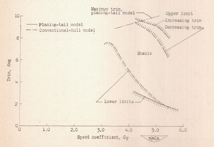
For a conventional hull, d(x) drops to zero at the step, and all virtual mass is concentrated on the forebody. For a planing tail, d(x) decreases smoothly through the afterbody, extending the virtual mass distribution and with it the pitch-damping lever arm. In matched towing tank tests, the conventional model showed the expected upper and lower porpoising boundaries with a narrow stable corridor between them. The planing-tail model showed only a lower boundary. No upper-limit porpoising was found at any speed or trim within the testable range.
The third consequence is trim behaviour during takeoff. The conventional hull starts at roughly 1 degree trim at rest, climbs sharply to a peak of about 8.5 degrees near hump speed, and then drops again as the afterbody clears the water. The total trim excursion is approximately 7.5 degrees. The planing-tail hull starts at about 6 degrees, because the deep step geometry sets a higher static attitude, and varies by only about 2 degrees through the entire takeoff run. The afterbody remains engaged throughout, preventing the sharp trim peak that occurs when a conventional hull’s afterbody breaks free and the resultant force jumps forward. For the pilot, this means a more predictable takeoff with less pitch management required. For the certification engineer, it means a smaller trim envelope that must be demonstrated clear of porpoising.
Why It Was Never Built
The practical advantages of the planing-tail hull were established in the NACA tank test programme between 1943 and 1956. Suydam’s 1948 comparison test (published as TN 2481 in 1952) provided the direct evidence against a conventional hull on the same airframe. Dawson’s parametric series (NACA Report 844 and TN 1101) mapped the effects of afterbody length, width, planform taper, step depth, keel angle, and chine length. A transonic seaplane design study in 1956 used a planing-tail hull at high length-beam ratios. The research was thorough. No production aircraft resulted.
The immediate reason was timing. By the mid-1950s, land-based runways had proliferated sufficiently to make flying boats operationally unnecessary for most military and civil roles. NACA’s seaplane hydrodynamics programme wound down as the agency’s resources shifted toward supersonic flight and, eventually, space. The planing-tail concept was shelved along with everything else in the flying boat research portfolio.
The deeper reason was manufacturing. The hull lines of a planing tail require compound curvature that varies continuously along the length. Every cross-section aft of the separation edge is geometrically distinct. In conventional aluminium construction with flat sheet panels and extruded stiffeners, this is difficult to produce and nearly impossible to produce repeatably. Hand-forming techniques existed. German flying boat manufacturers had demonstrated compound curvature in metal hulls through Klöppeln, a process of hand-beating sheet metal over shaped forms that produced elegant double-curved skins. But Klöppeln is artisan work. It does not scale, it does not repeat, and it was expensive even for the small production runs of the flying boat era.
A conventional stepped hull, by contrast, can be built almost entirely from flat or singly-curved panels joined at sharp chines and step lines. The forebody is prismatic or nearly so. The step is a straight transverse joint. The afterbody tapers simply to a point. Sheet metal shops can produce these shapes with standard equipment, and damaged panels can be replaced in the field by any competent metalworker with a set of shears and a rivet gun.
The choice between the two configurations was therefore never purely hydrodynamic. It was driven by the intersection of manufacturing capability, production economics, and field supportability, at a moment when the entire market for the product was disappearing. Under those circumstances, the rational decision was to stop investigating.
What Has Changed
Two things have changed since 1956 that reopen the question.
The first is manufacturing technology. Composite layup in female moulds reproduces compound curvature directly, with every part dimensionally identical to the tool. The tooling investment is significant, but per-part cost and geometric consistency are excellent. For metal construction, pressed panels from matched dies achieve compound curvature at automotive production rates. A middle path exists in panel approximation, where the continuous curvature is faceted into individually simple segments that each remain manufacturable with standard sheet metal equipment. The number of facets trades hydrodynamic fidelity against manufacturing simplicity and field reparability. All three approaches are proven in current aerospace or automotive practice.
The second change is computational capability. Savitsky’s method and Wagner’s theory, which together underpin most preliminary seaplane hull analysis, assume prismatic cross-sections. A planing tail violates this assumption by definition. In 1956, this meant that no reliable analytical method existed for predicting loads, pressures, or stability boundaries on a planing-tail hull without building a model and testing it. Today, computational fluid dynamics with free-surface tracking provides the spatial resolution needed to analyse non-prismatic hull geometries, and finite element methods handle the structural response to the resulting load distributions. The analytical gap that existed in the 1950s has closed.
What has not changed is the need for validation. The NACA towing tank data provides a starting point, but any new design will require its own test programme to demonstrate compliance with airworthiness requirements. The path to certification under CS-23 runs through rational analysis rather than the simplified conservative formulae, which assume conventional hull geometry. This raises the analytical burden, but the regulatory framework explicitly permits it.
If you find value in Engineering Airworthiness, consider subscribing for free.
If you think someone might benefit from it, feel free to share it.
References
Suydam, H.B. (1952). “Hydrodynamic Characteristics of a Low-Drag, Planing-Tail Flying-Boat Hull.” NACA TN 2481.
Dawson, J.R., Walter, R.C., and Hay, E.S. (1946). “Tank Tests to Determine the Effect on Planing-Tail Hulls of Varying Length, Width, and Plan-Form Taper of Afterbody.” NACA Report 844.
Dawson, J.R., McKann, R., and Hay, E.S. (1946). “Tank Tests to Determine the Effect of Varying Design Parameters of Planing-Tail Hulls. II.” NACA TN 1101.
Savitsky, D. (1964). “Hydrodynamic Design of Planing Hulls.” Marine Technology, Vol. 1, No. 1.
Wagner, H. (1932). “Über Stoß- und Gleitvorgänge an der Oberfläche von Flüssigkeiten.” ZAMM, Vol. 12.
Gudmundsson, S. (2014). General Aviation Aircraft Design. Butterworth-Heinemann, Appendix C3.
Yates, C.C., and Riebe, J.M. (1947). “Aerodynamic Characteristics of Three Planing-Tail Flying-Boat Hulls.” NACA TN 1306.
EASA CS-23 Amendment 5, Appendix I.