


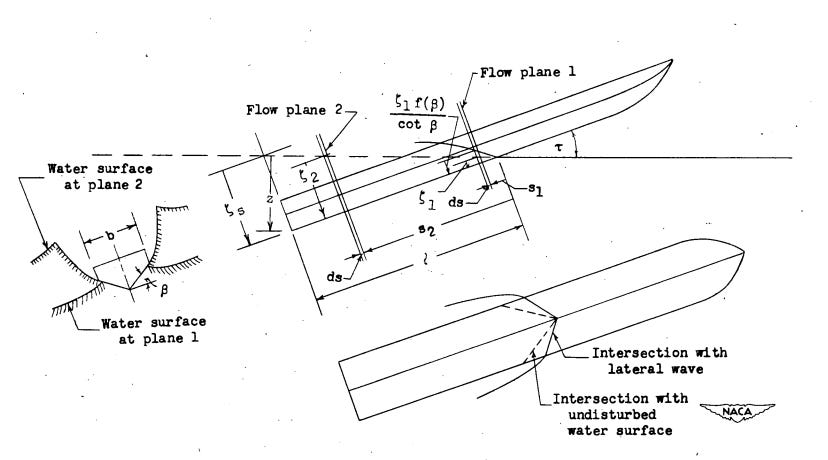
When a seaplane hull strikes the water surface, the load it experiences depends not on its own mass alone but on the virtual mass of water it must accelerate laterally as the wetted width grows. Wagner’s 1932 potential flow solution established that this virtual mass per unit wetted length scales with the square of the wetted half-width and with water density, and that the force during impact is dominated by the rate at which new water is recruited into the flow rather than by the deceleration of water already in contact. These results apply to a wedge cross-section at fixed geometry, but they do not address how the integrated behaviour of the complete hull changes when designers alter the most consequential geometric parameter available to them, namely the beam.
The Beam-Loading Coefficient
Benjamin Milwitzky at NACA Langley formulated the generalised theory of seaplane step-landing impact in 1948, published as Technical Note 1516, and extended it to the chine-immersed case in 1952 as Report 1103. Both papers organise the results around a single dimensionless group,
where W is the gross weight, ρ the water density, g gravitational acceleration, and b the hull beam at the step. Because beam enters in the third power, a 25 percent reduction in beam width while keeping weight constant roughly doubles CΔ, and conversely a 25 percent wider beam halves it. No other single geometric change has a similar leverage over the impact loads.
Milwitzky’s data from the Langley impact basin, covering hulls and floats across a roughly 25-to-1 range of beam loading, showed that American flying-boat practice of the 1940s sat predominantly below CΔ = 1, while floats on the same aircraft, carrying the same weight through a beam 60 to 70 percent narrower, routinely exceeded CΔ = 3. Some narrow hydroflap configurations tested for research purposes reached CΔ = 15 or higher, at which point the physics of the impact differs qualitatively from the conventional hull case rather than merely quantitatively.
Two Competing Effects During Impact
The hydrodynamic load during a step-landing impact arises from two sources, both traceable to the virtual mass derivation covered in the previous article. As the hull penetrates the water, the wetted width grows and each new strip of water that comes into contact must be accelerated laterally, so the force associated with this growth of virtual mass is proportional to the rate at which momentum is added to previously stationary water. Simultaneously, the water already in contact is decelerating with the hull, and the reaction to that deceleration contributes a second force component.
For most flying-boat hulls operating at CΔ < 1, the second term contributes roughly 10 percent of the total force at maximum load, and Milwitzky showed that omitting it introduces errors smaller than the experimental scatter in his impact basin data. For floats at CΔ > 3, both terms become comparable and neither can be dropped without consequence. The distinction matters because the two terms respond differently to changes in geometry. The expansion term grows with the rate of wetted width growth, which depends on the beam available for the virtual mass to expand into, while the deceleration term grows with the total virtual mass already accumulated. Both scale with b, but through different powers and at different phases of the impact, which is why the beam-loading coefficient proves so useful in encoding both effects in a single number.
The Approach Parameter
Beam loading alone does not determine the load at a given instant. The shape of the complete impact history also depends on the geometry of the approach, which Milwitzky captured in a second dimensionless quantity,
where τ is the trim angle and γ₀ the initial flight-path angle relative to the water surface. For a smooth-water step landing at 6° trim and a sinking speed of approximately 0.9 m/s at 150 km/h, K evaluates to roughly 7 to 8, with steeper approaches and wave landings reducing it toward the lower end of the practical range, which runs from about 0.2 to 10.
For a given value of CΔ, the generalised load-factor coefficient at maximum acceleration is a unique function of K alone, so all the effects of weight, dead rise, trim, velocity, and sinking rate collapse into these two numbers, and the maximum impact load follows from Milwitzky’s charts without further iteration. Landing on the flank of a wave steepens the effective flight-path angle and reduces K into the range 0.2 to 1.0, and the load rises accordingly. A seaplane that lands at 3g on smooth water can reach 6g or higher in moderate seas at the same approach speed and sink rate, because the wave slope alone shifts K far below its calm-water value.
Chine Immersion and the Load Peak
As the hull penetrates the water, the virtual mass expands laterally until the wetted width reaches the chines. Before that point, the growth of virtual mass continues as long as the hull geometry permits lateral expansion, but once the chines are immersed, the wetted width is fixed, the virtual mass stops growing, and the force mechanism changes to separated-flow behaviour rather than the expanding potential-flow solution, producing a much smaller force per unit additional penetration.
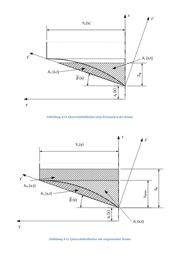
Whether this transition occurs before or after the maximum load is reached governs whether chine immersion has any practical effect on structural sizing. For hulls with CΔ < 1 landing at normal flight-path angles, the chines enter the water only after the load has already peaked, so the maximum load is fully determined by the pre-chine virtual-mass expansion and chine immersion is irrelevant to structural sizing, which describes the typical flying boat. At higher beam loadings the situation changes, and when CΔ exceeds approximately 2, particularly at lower values of K corresponding to steeper impacts or wave landings, the chines reach the waterline while the load is still rising. The force is then capped at the value corresponding to the moment of chine immersion, and Milwitzky’s calculations show a 30 percent reduction in maximum load factor for CΔ = 6 at 6° trim and a 5° flight-path angle relative to the no-chine prediction. At still higher beam loadings the reduction grows, though experimental validation of the theory becomes progressively thinner beyond CΔ = 8.
This behaviour is counterintuitive, since narrowing the hull increases beam loading, which might be expected to worsen the impact loads, yet for sufficiently narrow cross-sections the early chine immersion caps the peak force. The load relief comes with deeper penetration and a broader force-time history in which the peak is spread over a longer contact period, and the load path shifts from the keel to the chine region, which changes the structural sizing problem rather than simply reducing it.
Hull Configurations and Their Position in the Parameter Space
Large flying boat
A hull in the class of the Grumman HU-16 Albatross or the ShinMaywa US-2 carries 15,000 to 80,000 kg on a beam of 2.0 to 3.5 m at the step, placing CΔ in the range 0.3 to 0.8. At these values, chine immersion arrives after the load peak under all normal approach conditions, so the impact is governed entirely by virtual-mass expansion and the deadrise angle at the step is the primary geometric variable available to the designer for load control. Dead rise between 20° and 25° is the historical norm, representing a balance between planing efficiency at low speed and load mitigation during landing.
Light amphibian hull
Aircraft in the 800 to 3,000 kg class with purpose-built hulls, such as the Lake LA-4, carry their weight on a beam of 0.8 to 1.2 m, giving CΔ values that typically fall between 0.6 and 2.0, which places them near the boundary where chine immersion can influence the load peak under some approach conditions. At normal smooth-water approach angles the situation resembles the large flying boat, with chine effects arriving late, but in waves, where K can drop to 0.5 or below, chine immersion may cap the peak load by 10 to 20 percent for the heavier aircraft in this weight class.
Hull with sponsons or stub wings
A sponson adds a wide horizontal shelf at roughly waterline level, extending laterally beyond the hull keel structure, so the effective beam at first water contact is determined by the sponson width rather than by the keel geometry. Doubling the effective beam reduces CΔ by a factor of eight for the same aircraft weight, placing sponson configurations well below CΔ = 1 where the virtual mass grows so rapidly with penetration that the hull decelerates almost immediately. The load peaks at a shallow draught, at which point the wetted width is still far inside the sponson edges, and chine immersion never enters the picture. The structural consequence is that the sponson itself must be sized for the full uncapped impact load at its attachment to the main hull, without the relief that a narrower, higher-CΔ configuration might gain from early chine immersion.
Floats
Each float in a twin-float installation carries approximately half the aircraft weight during a symmetric step landing, and float beams range from about 0.25 to 0.45 m for light aircraft and 0.5 to 0.8 m for larger floatplanes, placing the beam-loading coefficient per float in the range of 2 to 12 for aircraft between 800 and 5,000 kg. This puts floats well into the regime where chine immersion precedes the load peak at most approach angles, and Milwitzky’s data show that at CΔ = 6 the maximum load factors are 25 to 30 percent lower than the no-chine prediction across the range of trims and flight-path angles that cover normal float operations. This explains why float structures that look, by weight-fraction standards, underbuilt compared to hull aircraft survive in service without incident.
The NACA theory in TN 1516 treats the hull as a prismatic wedge with constant cross-section, and the chine immersion analysis was validated only up to CΔ ≈ 8. Beyond that, buoyancy forces during deep penetration become non-negligible relative to the virtual-mass forces and the Milwitzky framework begins to deviate from experiment, so float designs at the upper end of the weight range, or in rough-water operations where steep effective flight-path angles drive deep penetration, require more detailed treatment than the generalised charts can provide.
What Changes Across the Parameter Space
The following table gives representative values for the four configurations discussed. The ranges are illustrative rather than exhaustive, and specific aircraft may fall outside them.
Implications for Design
The beam-loading coefficient tells the designer, before any detailed calculation, which physical regime the hull occupies and therefore which design variables are available for load control. For CΔ < 1, the deadrise angle is the primary lever, since increasing dead rise from 20° to 30° reduces the virtual mass per unit penetration and lowers peak loads by roughly 30 percent at the cost of reduced planing efficiency, while beam has limited direct utility as a load-control tool in this regime because the chines never come into play.
For CΔ > 2, beam itself becomes a load-control tool through its influence on when chine immersion occurs relative to the peak. A designer who can accept the structural consequences of a narrower, deeper-penetrating hull gains load relief that is not available at lower beam loadings, and float designers exploit this implicitly every time a float is dimensioned by water-handling and planing requirements rather than by impact loads, since the resulting high beam loading often delivers that relief through early chine immersion at no additional design cost.
The trade-off that beam loading encodes is not merely structural but operational, and it becomes visible when two aircraft of similar weight make different choices. The Consolidated PBY Catalina and the Grumman HU-16 Albatross both operate in the 16,000 to 17,000 kg class, but the Catalina’s hull beam at the step is roughly 3.1 m while the Albatross hull is visibly narrower in the range of 2.3 m. Because beam enters the denominator in the third power, even this moderate difference shifts the Albatross well above the Catalina in the CΔ parameter space. The consequence shows up in service so that the Catalina planes more efficiently at low speed and gets off the water in shorter distances, while the Albatross, whose narrower and deeper-V hull penetrates further before the virtual mass arrests it, tolerates open-ocean swells that would overstress the Catalina’s wider, flatter bottom. That the Albatross routinely needed JATO rockets for takeoff in heavy seas is the visible cost of a hull optimised for the other end of the parameter space, where seaworthiness rather than planing efficiency governs the design.
There is a further asymmetry between flat and deep-V hulls that the equation of motion makes legible. The force during impact has the structure
The second term is quadratic in the sink rate ż. For a flat-bottomed hull, ∂m_w/∂z is large from the first moment of contact, because the waterplane area grows immediately with penetration, so this term penalises high sink rates quadratically rather than linearly. Doubling the sink rate at touchdown quadruples the contribution of this term, whereas a deep-V hull, where ∂m_w/∂z grows slowly with penetration, is comparatively forgiving of the same excess. Sink-rate limits in flight manuals are therefore structurally more consequential for flat-keel configurations than for their deep-V counterparts, because the same exceedance in ż produces a disproportionately larger load on the flatter hull.
The approach parameter K interacts with beam loading in a way that matters for operational envelope definition. An aircraft that operates well within its structural limits on smooth water may approach its structural margins in waves, not because the aircraft is heavier or the pilot lands faster, but because the effective K of a wave landing reduces the load-relief effect of a given beam-loading coefficient. Seaworthiness limits defined purely by hull geometry without reference to K are therefore potentially non-conservative in the conditions they are most likely to encounter.
If you find value in Engineering Airworthiness, consider subscribing for free.
If you think someone might benefit from it, feel free to share it.
References
Wagner, H. (1932). “Über Stoß- und Gleitvorgänge an der Oberfläche von Flüssigkeiten.” Z.f.a.M.M., Bd. 12, Heft 4, pp. 193–215.
Milwitzky, B. (1948). “A Generalised Theoretical Investigation of the Landing Loads of a Helicopter Float or a Seaplane With Arbitrarily Shaped Hull Cross-Sections and Arbitrary Attitudes.” NACA TN 1516.
Milwitzky, B. (1952). “Generalised Theory for Seaplane Impact.” NACA Report 1103.
Schnitzer, E. (1952). “Theory and Procedure for Determining Loads and Motions in Chine-Immersed Hydrodynamic Impacts of Prismatic Bodies.” NACA TN 2813.
Höltken, M. (2019). “Bestimmung und Optimierung der hydrodynamischen Eigenschaften und Lasten an Schwimmwerken leichter amphibischer Flugboote.” M.Sc. Thesis, RWTH Aachen.